After building half a dozen speakers, I have converged on a way to build my passive crossovers. I am specifically referring to what needs doing after the crossover circuit has been designed and the parts have been procured. What next?
The board
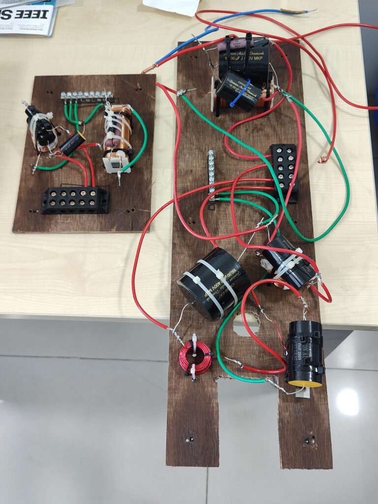
I assemble each crossover on a sheet of 6mm thick plywood. This sheet is mounted on the rear wall of the speaker with small standoffs. Each standoff is actually a small nylon buffer of the kind used below the legs of chairs and tables, to help us move the furniture easily. Each standoff gets a stainless steel screw and a washer.
Arranging the components
I separate out the components of a crossover into clusters or groups. Each group has one inductor. That’s it. A group of components has one inductor, plus any capacitors and resistors which will be directly connected to that inductor.
See a crossover circuit below:
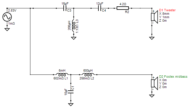
Looking at the circuit, it’s easy to group the components based on my one rule: each group must have zero or one inductor, not more. The other components must be those which are “in close connection” with that inductor and with each other. Following this rule, I can make the following groups:
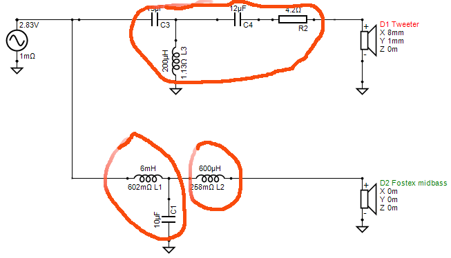
Note how one group has just one inductor. I made three groups, I could have made four — I could have put C4 and R2 into a fourth group. It’s all up to you — whatever works.
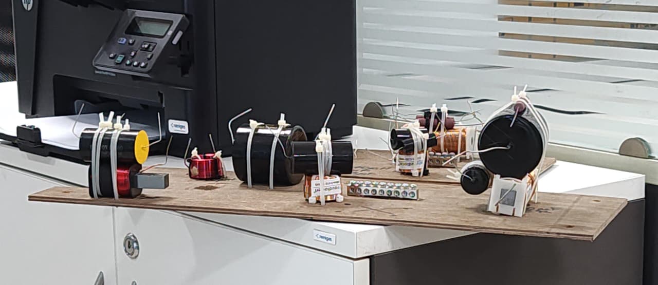
Then I use cable ties to tie the components of each group together. So, each group becomes a physical bundle.
Mounting the components
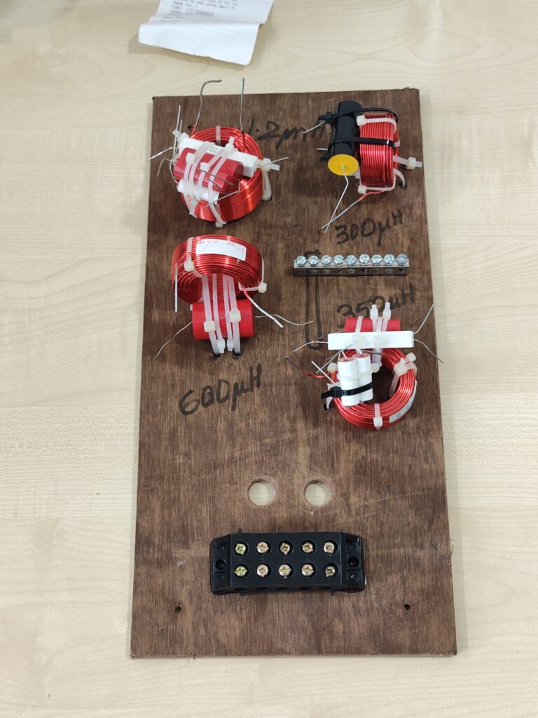
I mount each group onto the board using cable ties. I place each group on the board to ensure that adjacent inductors have their axes at right angles to each other. If I can’t follow the right-angle rule, then I place the groups at least six inches apart, preferably eight inches.
I place the groups on the board, make markings with felt pens, and get a layout or map done of the groups on the board. Then I drill holes for the cable ties to pass through the board. Finally, I fix each group at its designated location, with its designated orientation, on the board.
Wiring
A crossover needs wires
- to connect components to each other when they are a few inches apart
- to connect the outgoing leads from the crossover to the drivers. A four driver speaker will have eight outgoing wires.
- to connect the inputs from the terminal blocks (the banana sockets, the binding posts, whatever) which bring the electrical power from the amplifier output. A speaker which is designed for bi-wiring and bi-amping will have four wires coming from the input binding posts to the crossover.
So, there are lots of wire. I have standardised on Polycab or Finolex 2.5 sqmm insulated multi-strand mains electrical cable for all my internal wiring of a speaker. I use only pure OFC wire, not copper coated aluminium. I have bootlace ferrules which fit these wires, and a wire stripper set up to strip the insulation from wires of this thickness. Standardisation allows me to work fast and build good quality wiring because all the little accessories are ready for this size.
I buy several metres of red cable, similar length of black, periodically, for my speaker projects.
The ground block
A typical crossover gets lots of points which need to be connected to a common or ground point. See the crossover circuit above:
- one ground ref line comes in from the amplifier
- one ground line from the midbass driver
- one ground line from the tweeter
- C1
- L3
This makes five “things” which need to connect together in a common ground point. More complex crossovers can have twice this count even for 2-way designs. How do you join together a dozen high current wires?
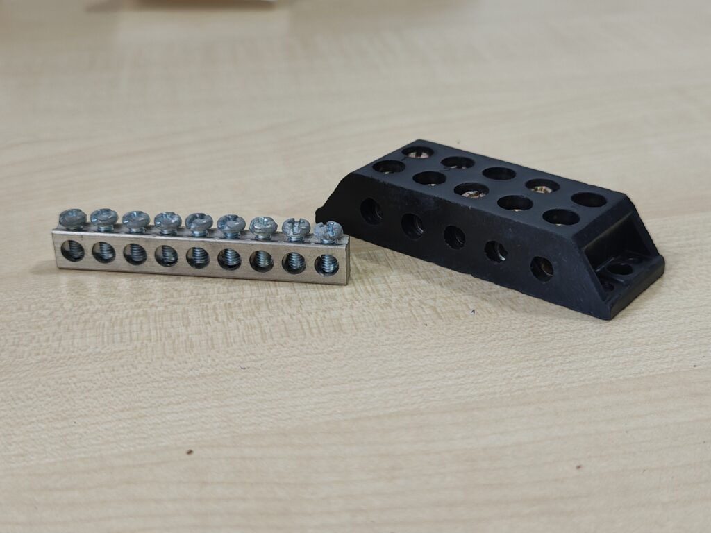
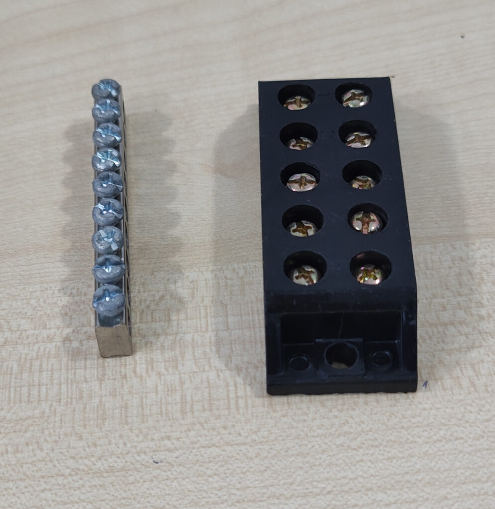
In my initial days, I used to solder them all together into one massive ball of copper and solder, an ugly lump perhaps a centimetre in diameter. Today, I use a terminal strip with 10 or more screws. I can insert wires into the strip and tighten its screw.
I fix this ground block with Araldite onto the crossover board.
Ingress-egress wiring
A crossover board will have internal wiring on the board, plus wires coming in and leaving the board. For all such ingress and egress wiring, it’s good to have a terminal connector system which will let me attach and detach wires to the board using just a screwdriver, not soldering. To enable this, I have a barrier strip which lets me connect wires like this. I use bakelite terminal strips with 30-amp rated connectors which can be tightened using screws.
I fix the terminal strip onto the crossover board using Araldite.
Wire ends and screw terminals
If you insert bare copper wire into a screw terminal and tighten the screw, the connection becomes very tight. However, this does not last. Copper is flexible, and with time and pressure, it “flows” very slowly, over the next few years, to make way under pressure. This makes the pressure joint less tight, and after a decade or two, loose connections may emerge. So I use bootlace ferrules and a crimping tool to prepare each wire end before it enters the screw terminal. This pre-crimping puts the copper strands into a pre-stressed crimp, which will last a hundred years. I then insert this prepared end into the screw terminal and tighten.
The photos below show actual 2.5 sqmm electrical wire with their ends crimped with bootlace ferrules.
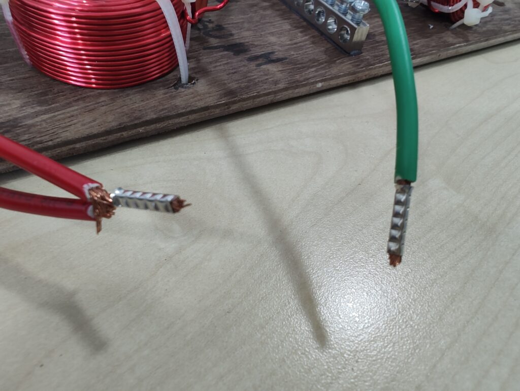
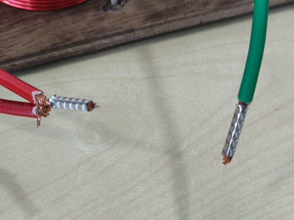
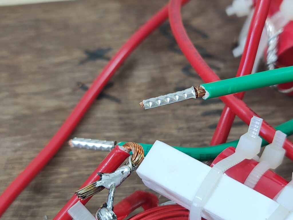
These bootlace ferrules from RS India seem to be identical to what I use. https://in.rsdelivers.com/product/rs-pro/rs-pro-uninsulated-crimp-bootlace-ferrule-10-mm-32/1787352 The pins are 10mm long, tinned copper, uninsulated, and their diameter is just slightly wider than what’s needed to insert a 2.5 sqmm multi-strand wire. They are just small pieces of copper tube, basically.
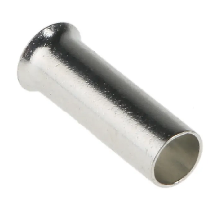
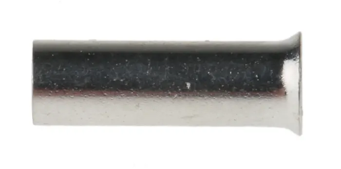
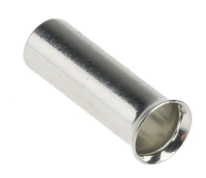
You can get insulated ones too, which look nicer but don’t add any value for crossover builds. These things are now available at very low prices on Amazon India, together with a crimping tool (A bootlace ferrule crimper is quite different from one used for crimping, say, QC connectors to cables.)
-x-x-x-x-x-