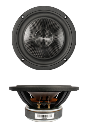
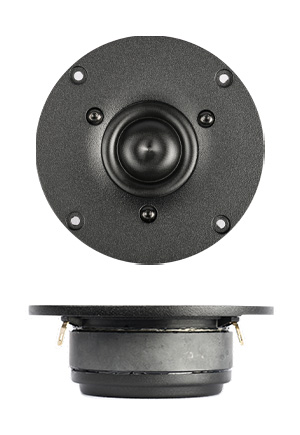
This continues the tradition of the Asawaris, with an MTM design and two 6.5″ midbass drivers. In this case it’s the SB17CRC carbon fibre drivers and the SB29RDAC ring radiator tweeter.
The key difference from the first five Asawaris is that this is a standmount.
Drivers
The midbass drivers used here are interesting. The carbon-fibre cone construction, with a Rohacell structure, makes them very light and stiff but also quite well damped. Aluminium cones are light and stiff too, but ring like a bell. This one doesn’t. Therefore, this cone material is expected to combine the damping properties of paper with the stiffness and low distortion of metal cones.
The tweeter is a soft-sounding ring radiator, which should be able to complement the well-damped sound of the midbass cones. This ring radiator has low distortion to quite low frequencies, thus allowing low Fc which is needed for MTM designs.
The enclosure
Putting two 4-Ohm midbass drivers in series gives me a relatively easy 8-Ohm load to drive, so I did that, and Unibox gave me a box model as follows:
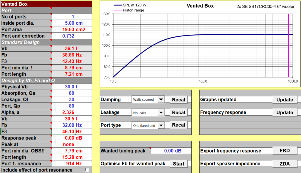
This told me:
- I would build a box with a 30-litre net internal volume,
- I’d use one 2-inch diameter port, with one flared end, and
- the port would be 15.28cm long
- This would give me a smooth drop-off of the low frequency extension, and I’d probably get somewhere between 30-35Hz as the in-room low frequency limit from this speaker. That’s plenty for a standmount — no acoustic music other than church organs go below about 35 Hz anyway.
I try to tune both sealed and bass reflex boxes to give me a gradual drop-off, sort of like a Qtc of 0.6 to 0.65, and I believe that the F10 point of that drop-off curve will give me the limit of my in-room bass-extension, because the room gain will counteract the bass fall-off and F10 is a realistic limit. (F10 is the frequency at which the bass falls off 10dB below the flat portion.) Applying that same rule of thumb, my modeled curve’s flat portion for the Asawari VI is at 110dB, which makes F10 the frequency at which the SPL drops to 100dB. From the graph, I can see that it’ll be somewhere betweeen 30-35Hz, take your pick.
Designing the enclosure, I use the following steps to arrive at the box internal dimensions. I’ve used these in earlier projects too.
- I see the diameter of the cutout for the driver. In the case of the SB17 series from SB Acoustics, it’s 145mm.
- My baffle is two sheets of 25mm thickness. We first do the maths for the outer sheet or top sheet. I keep half the depth of the top sheet as a straight cylindrical cut, and flare out the balance half depth at 45 degrees. This means that my cutout will be 12.5mm deep as a cylinder, and the balance 12.5mm as a bevelled circle at 45 degrees.
- This means that the radius of the cutout on the inner edge of the top baffle sheet will be larger than the outer edge by 12.5mm. In other words, the inner surface will see a circle 25mm larger in diameter than the outer surface. Since the outer surface was a circle of 145mm, the inner surface will see a circle of 145+25 = 170mm.
- There is a second sheet of the front baffle, as mentioned before. This too is 25mm thick. The bevelling for this cutout is the full depth of the sheet, again at 45 degrees. This means that the cutout will start with a diameter of 170mm and exit (on the inner surface) with a diameter of 220mm.
- Now I know that the midbass drivers will have 220mm cutouts (at their widest), and I keep the enclosure width equal to this. So my enclosure width will be 220mm internally. The idea is that the rear wave of the midbass drivers should have unrestricted opportunity to open out into the enclosure. (I follow the same approach for woofers, midranges, and midbass drivers of all projects. Tweeters have no rear wave, and therefore need a straight cylindrical cut.)
This decides the inner width. The inner height is decided by the distance between drivers. The Asawaris are MTM designs, so they need tight packing in the vertical direction. I placed gaps of 10mm between the front flanges of the drivers. Therefore:
- Top midbass driver: 170mm diameter of outer flange
- inter-driver gap: 10mm
- Tweeter: 100mm diameter of front plate
- inter-driver gap: 10mm
- Lower midbass driver: 170mm diameter again
This means that the vertical distance for all the drivers put together is 170+10+100+10+170 = 460mm. Add 50mm additional height at the top and 50mm at the bottom, and I got an internal height of 560mm.
Thus my enclosure internal dimensions were 560mm x 220mm. The depth was decided by the need to arrive at a 30-litre volume. To arrive at this, I calculated the volume of each midbass driver’s internals (cone + magnet), the volume of the braces (four horizontal strips as horizontal braces, one vertical brace), volume of the BR duct (15cm long, 5cm diameter), subtracted these from the overall volume, and arrived at a 30-litre volume if I kept the internal depth to be 290mm.
The insides of the box therefore are 220 x 560 x 290, all in mm. Now I could draw the three views of the box. All dimensions in the drawings below are in cm, not mm. The first is the external view.

I tried to add some aggressive bevelling on the two sides of the tweeter, to minimise edge diffractions. I continued the bevelling around the midbass drivers too, just “for the looks”. As the side view shows, the front baffle is 50mm thick, and the rear wall (baffle?) is a single sheet, hence 25mm.
The internal details are as follows:

I pasted line drawings of the three drivers from their datasheets, just to give a clearer visual idea of the internals. The four horizontal braces are shown edgeways, at equal intervals. Each brace is made of 20mm plywood, and is a strip 6cm wide and 22cm long, since is stretches from wall to wall. There is also a vertical brace, which is not shown here. It will form crosses with the four horizontal braces.
In the front baffle, the red circles are the diameters of the outer flanges or front plates of the drivers (170mm for the midbass, 100mm for the tweeter). The solid-line black circles inside them are the cutouts (145mm for the midbass, 70mm for the tweeter). The larger dotted-line circles are the bevelled, opened-out cutouts (220mm for the midbass) as they will appear from the inside.
Going by my past experience, these boxes are completely inert by design, and will not vibrate when playing music at any reasonable domestic-listening levels. They will be lined internally on all surfaces with absorbent acoustic foam lining of the kind used in recording rooms.
(Construction photos will come here.)
Measurements
Will go here. Measurements will be shown separately for the two tweeters.
Crossover
The stock configuration
Will go here.
Swapping in the SB29SDAC
Will go here.